


Cylindrical + Planetary gears
Cylindrical + Planetary gears
Module List P1 (Basic)
Module List P1 (Basic)
ZPK Cylindrical gears
Calculation of cylindrical gear pairs and single gears
Calculation of geometry, control measurements (DIN 3960, DIN 3962, DIN 3963, DIN 58400)
Tolerances as specified in updated ISO 1328-1,2:2020
Reference profiles according to DIN 867, JIS 1701-1, deep tooth forms and short cut toothing, machining addition, grinding of tooth root
Strength calculation for a cylindrical gear, either as specified in ISO 6336 (module ZA10), DIN 3990 (module ZA11), AGMA 2001 (module ZA12), VDI 2545 (module ZA17), VDI 2736 (module ZA21) or GOST 21354-87 (module ZA22)
Input of speed for epicyclic gears configuration
Calculation of tooth friction and power loss according to Niemann
Flash temperature progression
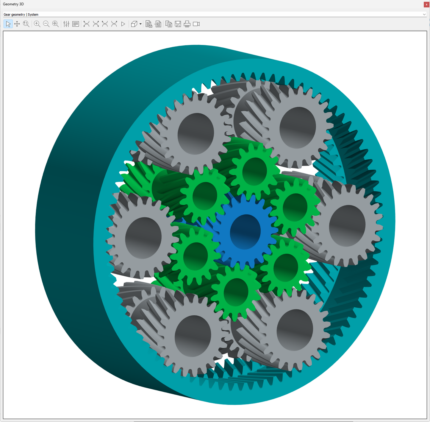
Calculation and 2D and 3D display of the tooth form for external and internal toothing
Scuffing according to DIN 3990 and ISO/TS 6336-20/21
Micropitting according to ISO/TS 6336-22 (Method B)
Calculation of case hardening depth according to FVA 271
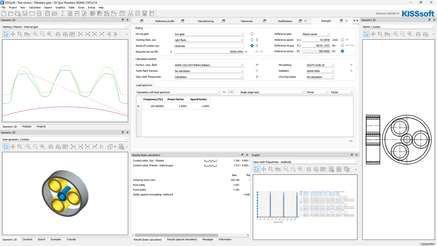
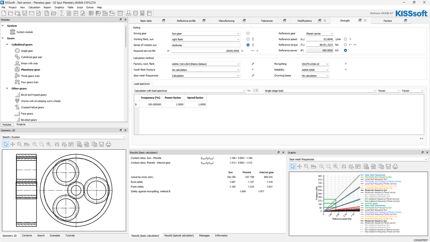
Calculation of gear mesh frequencies, assembly phase frequencies and hunting tooth frequencies
Input of individual flank line modifications per tooth
Generation of variants for modifications
Arc of circle and spline approximation for 2D Export (requires module CA1)
Extended 2D and 3D display of the tooth form (module ZY1)
Tip shortening for involute or imported tooth forms
Animation of meshing gears, simultaneous display of more than one machining step, measuring function in the graphic, function for saving data for A – B comparison,
collision check, marking of contact point, marking of collision
Manual input of active tip and active root circles in the single gear calculation
Output of manufacturing drawings
Extensive material database
Save tools to the database and compare with existing tools
Contains this module: ZY1
Rights: Z01, Z01z, Z04b, Z04c, Z05i, Z05t, Z05v, Z19e, Z19m
ZA10 Strength according to ISO 6336:2019 and ISO 6336:2006 (replaced)
Rights: Z02a
ZA1 Planetary gears, three gears, four gears
Rights: Z01a, Z19g
ZY1 Extended tooth form display
For 2D and 3D graphics, animation of meshing gears, simultaneous display of more than one machining step, measuring function in the graphic, function for saving data for A – B comparison, tooth form and tool in normal section, collision check, marking of contact point, marking of collision
Rights: Z05x, Z05j, Z05k
ZA5 Sizing functions and special calculations
Sizing of profile shift using different criteria
Calculation of profile shift and tooth thickness allowance taken from measured tooth geometry, pre-machining tools with grinding stock, topping tools
Sizing of the reference profile for a required transverse contact ratio
Rough sizing of modifications (microgeometry), tip and root relief (linear, progressive and logarithmical), crowning and helix angle modification sizing, taking into account axis inclinations as specified in ISO 6336-1, Annex B or in ISO 6336-1, Annex E (requires module ZA35)
Report for tolerances according to ISO 1328, DIN 3961, DIN 58405, BS 436, AGMA 2001 or AGMA 2015
Calculation with manufacturing profile shift
Sizing of center distance to take into account balanced specific sliding
Profile and flank line diagrams (K diagrams)
Rights: Z01x, Z15, Z19a, Z19d, Z19h, Z19l, Z19n
Module List P2 (Designer)
Module List P2 (Designer)
ZPK Cylindrical gears
Calculation of cylindrical gear pairs and single gears
Calculation of geometry, control measurements (DIN 3960, DIN 3962, DIN 3963, DIN 58400)
Tolerances as specified in updated ISO 1328-1,2:2020
Reference profiles according to DIN 867, JIS 1701-1, deep tooth forms and short cut toothing, machining addition, grinding of tooth root
Strength calculation for a cylindrical gear, either as specified in ISO 6336 (module ZA10), DIN 3990 (module ZA11), AGMA 2001 (module ZA12), VDI 2545 (module ZA17), VDI 2736 (module ZA21) or GOST 21354-87 (module ZA22)
Input of speed for epicyclic gears configuration
Calculation of tooth friction and power loss according to Niemann
Flash temperature progression
Calculation and 2D and 3D display of the tooth form for external and internal toothing
Scuffing according to DIN 3990 and ISO/TS 6336-20/21
Micropitting according to ISO/TS 6336-22 (Method B)
Calculation of case hardening depth according to FVA 271
Calculation of gear mesh frequencies, assembly phase frequencies and hunting tooth frequencies
Input of individual flank line modifications per tooth
Generation of variants for modifications
Arc of circle and spline approximation for 2D Export (requires module CA1)
Extended 2D and 3D display of the tooth form (module ZY1)
Tip shortening for involute or imported tooth forms
Animation of meshing gears, simultaneous display of more than one machining step, measuring function in the graphic, function for saving data for A – B comparison,
collision check, marking of contact point, marking of collision
Manual input of active tip and active root circles in the single gear calculation
Output of manufacturing drawings
Extensive material database
Save tools to the database and compare with existing tools
Contains this module: ZY1
Rights: Z01, Z01z, Z04b, Z04c, Z05i, Z05t, Z05v, Z19e, Z19m
ZA10 Strength according to ISO 6336:2019 and ISO 6336:2006 (replaced)
Rights: Z02a
ZA1 Planetary gears, three gears, four gears
Rights: Z01a, Z19g
ZY1 Extended tooth form display
For 2D and 3D graphics, animation of meshing gears, simultaneous display of more than one machining step, measuring function in the graphic, function for saving data for A – B comparison, tooth form and tool in normal section, collision check, marking of contact point, marking of collision
Rights: Z05x, Z05j, Z05k
ZA5 Sizing functions and special calculations
Sizing of profile shift using different criteria
Calculation of profile shift and tooth thickness allowance taken from measured tooth geometry, pre-machining tools with grinding stock, topping tools
Sizing of the reference profile for a required transverse contact ratio
Rough sizing of modifications (microgeometry), tip and root relief (linear, progressive and logarithmical), crowning and helix angle modification sizing, taking into account axis inclinations as specified in ISO 6336-1, Annex B or in ISO 6336-1, Annex E (requires module ZA35)
Report for tolerances according to ISO 1328, DIN 3961, DIN 58405, BS 436, AGMA 2001 or AGMA 2015
Calculation with manufacturing profile shift
Sizing of center distance to take into account balanced specific sliding
Profile and flank line diagrams (K diagrams)
Rights: Z01x, Z15, Z19a, Z19d, Z19h, Z19l, Z19n
ZA3 Rough sizing macrogeometry
for gear pairs and planetary gear stages
Sizing according to required safeties, determination of the center distance and facewidth for solutions with the same torque capacity, display of multiple variants, specification of total weight
Rights: Z03
ZA4 Fine sizing macro geometry
for gear pairs and planetary gear stages, three gears, and four gears
Variation of the module, number of teeth, profile shifts, pressure angle, etc.
Calculation of all executable variants, taking into account the installation constraints of planet gears
Automatic sizing of deep tooth forms (requires module ZA5)
Calculation of transmission error for all variants (requires module ZA30)
Specification of cutter and pinion-type cutter lists per gear
All solutions are classified on the basis of different criteria
Display of results in tables and graphics
Rights: Z04, Z04a
ZZ1 Load spectra and transmittable torque
Calculation of transmittable power with and without load spectrum
Calculation of service life with and without load spectrum
Calculation of safeties with load spectrum (for cylindrical, bevel, and cross helical gears)
Taking into account the direction of rotation of the individual stages, and their load direction (for cylindrical gears)
Graphical display of speed and torque classes
Rights: Z16, Z16a, Z18, Z18a, K23
Module List P3 (Expert)
Module List P3 (Expert)
ZPK Cylindrical gears
Calculation of cylindrical gear pairs and single gears
Calculation of geometry, control measurements (DIN 3960, DIN 3962, DIN 3963, DIN 58400)
Tolerances as specified in updated ISO 1328-1,2:2020
Reference profiles according to DIN 867, JIS 1701-1, deep tooth forms and short cut toothing, machining addition, grinding of tooth root
Strength calculation for a cylindrical gear, either as specified in ISO 6336 (module ZA10), DIN 3990 (module ZA11), AGMA 2001 (module ZA12), VDI 2545 (module ZA17), VDI 2736 (module ZA21) or GOST 21354-87 (module ZA22)
Input of speed for epicyclic gears configuration
Calculation of tooth friction and power loss according to Niemann
Flash temperature progression
Calculation and 2D and 3D display of the tooth form for external and internal toothing
Scuffing according to DIN 3990 and ISO/TS 6336-20/21
Micropitting according to ISO/TS 6336-22 (Method B)
Calculation of case hardening depth according to FVA 271
Calculation of gear mesh frequencies, assembly phase frequencies and hunting tooth frequencies
Input of individual flank line modifications per tooth
Generation of variants for modifications
Arc of circle and spline approximation for 2D Export (requires module CA1)
Extended 2D and 3D display of the tooth form (module ZY1)
Tip shortening for involute or imported tooth forms
Animation of meshing gears, simultaneous display of more than one machining step, measuring function in the graphic, function for saving data for A – B comparison,
collision check, marking of contact point, marking of collision
Manual input of active tip and active root circles in the single gear calculation
Output of manufacturing drawings
Extensive material database
Save tools to the database and compare with existing tools
Contains this module: ZY1
Rights: Z01, Z01z, Z04b, Z04c, Z05i, Z05t, Z05v, Z19e, Z19m
ZA10 Strength according to ISO 6336:2019 and ISO 6336:2006 (replaced)
Rights: Z02a
ZA1 Planetary gears, three gears, four gears
Rights: Z01a, Z19g
ZY1 Extended tooth form display
For 2D and 3D graphics, animation of meshing gears, simultaneous display of more than one machining step, measuring function in the graphic, function for saving data for A – B comparison, tooth form and tool in normal section, collision check, marking of contact point, marking of collision
Rights: Z05x, Z05j, Z05k
ZA5 Sizing functions and special calculations
Sizing of profile shift using different criteria
Calculation of profile shift and tooth thickness allowance taken from measured tooth geometry, pre-machining tools with grinding stock, topping tools
Sizing of the reference profile for a required transverse contact ratio
Rough sizing of modifications (microgeometry), tip and root relief (linear, progressive and logarithmical), crowning and helix angle modification sizing, taking into account axis inclinations as specified in ISO 6336-1, Annex B or in ISO 6336-1, Annex E (requires module ZA35)
Report for tolerances according to ISO 1328, DIN 3961, DIN 58405, BS 436, AGMA 2001 or AGMA 2015
Calculation with manufacturing profile shift
Sizing of center distance to take into account balanced specific sliding
Profile and flank line diagrams (K diagrams)
Rights: Z01x, Z15, Z19a, Z19d, Z19h, Z19l, Z19n
ZA3 Rough sizing macrogeometry
for gear pairs and planetary gear stages
Sizing according to required safeties, determination of the center distance and facewidth for solutions with the same torque capacity, display of multiple variants, specification of total weight
Rights: Z03
ZA4 Fine sizing macro geometry
for gear pairs and planetary gear stages, three gears, and four gears
Variation of the module, number of teeth, profile shifts, pressure angle, etc.
Calculation of all executable variants, taking into account the installation constraints of planet gears
Automatic sizing of deep tooth forms (requires module ZA5)
Calculation of transmission error for all variants (requires module ZA30)
Specification of cutter and pinion-type cutter lists per gear
All solutions are classified on the basis of different criteria
Display of results in tables and graphics
Rights: Z04, Z04a
ZZ1 Load spectra and transmittable torque
Calculation of transmittable power with and without load spectrum
Calculation of service life with and without load spectrum
Calculation of safeties with load spectrum (for cylindrical, bevel, and cross helical gears)
Taking into account the direction of rotation of the individual stages, and their load direction (for cylindrical gears)
Graphical display of speed and torque classes
Rights: Z16, Z16a, Z18, Z18a, K23
ZA24 Tooth root stresses with 2D FEM
Calculation of tooth root stresses for cylindrical gear pairs (with straight or helical teeth)
Calculation with integrated FEM Solver CM2®
FEM results displayed in KISSsoft
Rights: Z38a
ZA30 Contact analysis for cylindrical gears
taking into account flank modifications and shaft deformation
Tooth flank fracture according to ISO/TS 6336-4:2019 (requires module ZZ4)
Calculation of the excitation force according to FVA-No. 487
Calculation of path of contact under load
Graphical display of the results in the excitation force, efficiency, forces and stresses groups
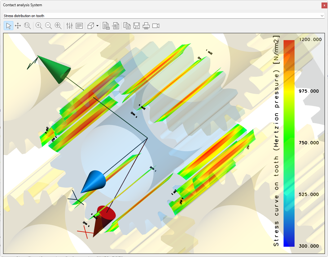
Calculation and display of Hertzian pressure, contact pattern and tooth root stresses along the actual tooth flank
Load-free contact pattern and display of the assembly contact pattern
Calculation with conical profile shift
Calculation of contact stiffness and transmission error under load, based on the actual tooth form
Display of specific sliding, sliding velocity and sliding factors for gears under load from actual tooth form
Display of friction power and local heat generation along the meshing
Wear calculation for plastic (dry run) and steel (cold wear)
Calculation and display of the progression of wear
Calculation of safety against micropitting according to ISO/TS 6336-22
Calculation of lubrication gap according to ISO/TS 6336-22 and AGMA 925 with actual normal force
Calculation of power loss and speed across the meshing
Rights: Z24, Z25, Z27, Z30, Z31, Z31a, Z32, Z32b, Z32c, Z36, Z39a, Z39b, Z39c, Z39d and K05w
ZA35 Face load factor KHbeta according to ISO 6336-1, Appendix E
Calculation of gaping and load distribution while taking into account flank modifications and shaft deformation
Tolerance variations with (+/-)fma and (+/-)fhb
Results are displayed in graphics and reports
Results for individual planets can be output
Rights: Z02c
ZZ4 Tooth flank fracture for cylindrical and bevel gears
For cylindrical gears according to ISO/TS 6336-4
For bevel and hypoid gears according to ISO/DTS 10300-4:2019 (draft) (requires modules ZC2 or ZC9)
Rights: Z07k
ZA34 Planetary stage contact analysis
taking into account flank modifications and shaft deformation
Floating sun wheel
All other functionalities as described in ZA30
Rights: Z24, Z25, Z27, Z30, Z31, Z31a, Z32c, Z34, Z36, Z39a, Z39b, Z39c, Z39d, K05w
General Description
General Description
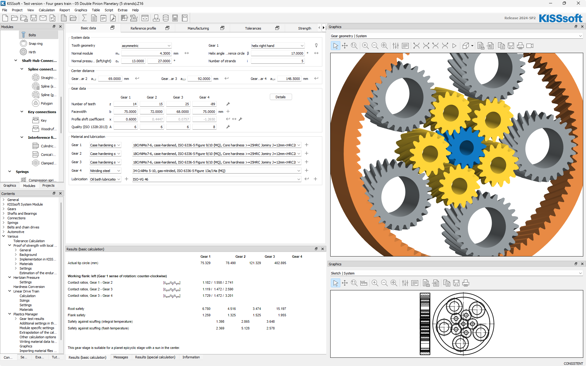
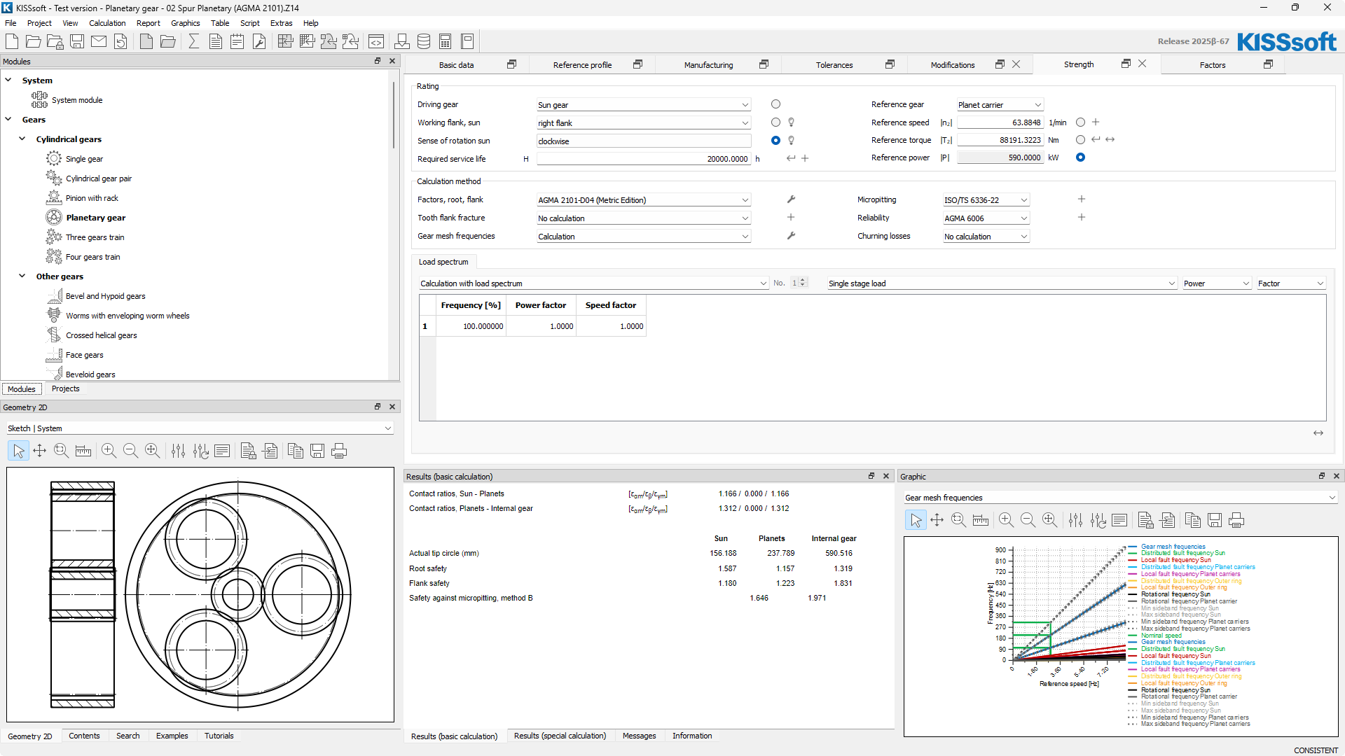
Planetary gears
Overview
- Based on helical gear calculation modules
- Calculation of planet pin location for non-evenly spaced planets
- Influence of rim thickness of ring gear and planet gears considered
- Assembly check
- Sizing function for load distribution factor along AGMA 6123
- Rough and fine sizing function
Strength rating, planets
- DIN 3990 method B, DIN 3990 method B with YF along method C, DIN 3990 Part 41 (vehicles)
- ISO 6336:2006 and ISO 6336:2019
- Static rating against yield
- AGMA 2001-C95, AGMA 2101-D04, AGMA 2001-D04
- AGMA 6004-F88, AGMA 6011-J14, API 613 :2021, AGMA 6014-B15, AGMA 6015-A13, GOST 21354-87
- Plastic gears along Niemann, VDI 2545, VDI 2545 modified, VDI2736
- BV / Rina FREMM3.1, Rina 2010, DNV41.2, Loyds Register 2013
- ISO 13691:2001 (high speed gears)
- For nominal load or load spectrum
- Planet system reliability
- Micropitting rating along ISO/TS 6336-22, scuffing rating along ISO 6336-20, ISO 6336-21, DIN 3990, AGMA 925
- Flank fracture rating along ISO/TS 6336-4 and case crushing rating along DNV 41.2
Kg calculation
- For systems with perfect pin position or for pins with positioning error
- Quasi-static load distribution neglecting dynamic effects
- Sun may be floating or stationary
- Kg is calculated for momentary force equilibrium for different meshing positions
- Considering system equilibrium for in-phase and out-of-phase systems
- Phasing check
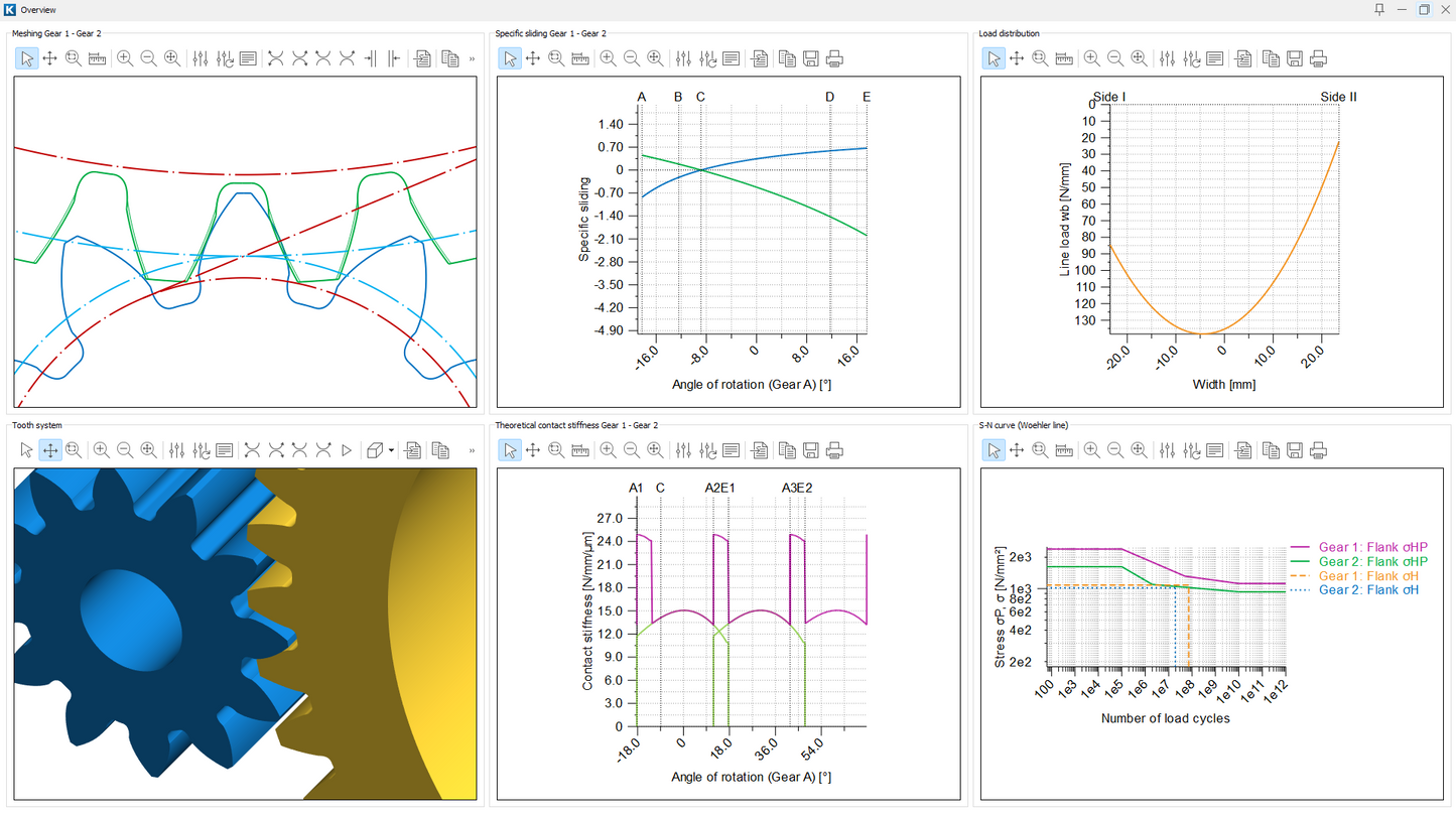
Planetary tooth contact analysis
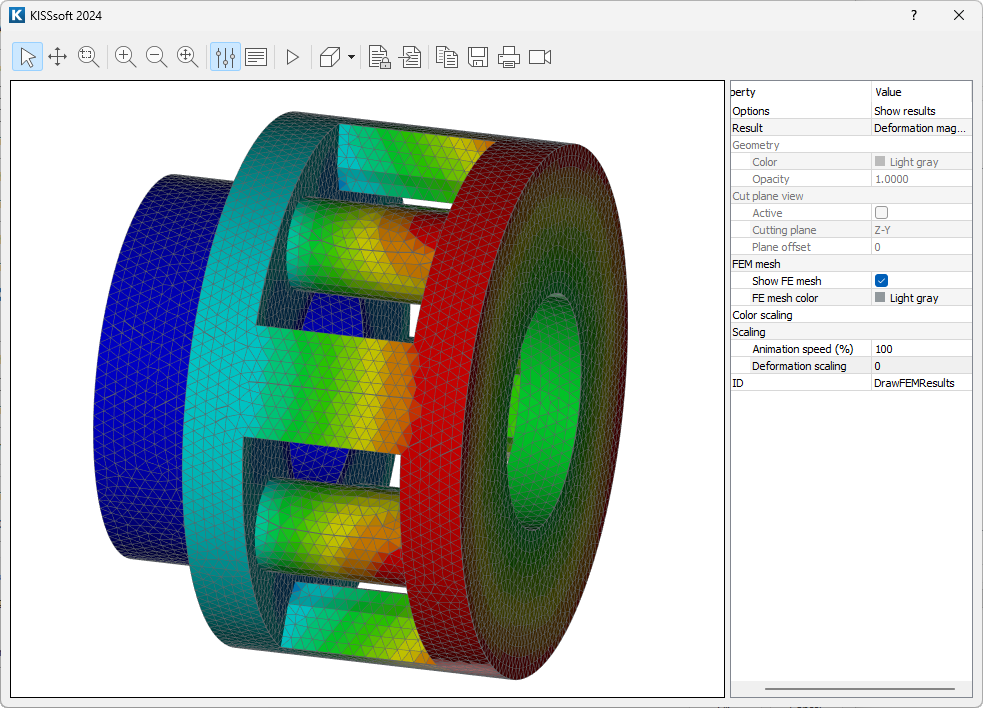
FEM calculation of planetary carrier
- Planetary carrier torsion is calculated inside KISSsoft with FEM
- Salome / Code Aster is used as pre-processor and solver, using Python scripts
- Based on parameterized model of the carrier (import of carrier geometry is not directly possible)
- Mesh generation is automatic
- Includes sizing function for planetary carrier geometry
- Results may also be directly imported from FEM results file
Ring gear deformation
- In case of ring gears supported only on one side, the conical deformation may be considered for the planet – ring gear mesh
Sun gear arrangement
- Floating or fixed sun gear
- In case of floating sun gear, quasistatic momentary equilibrium is calculated
Link to shaft calculations
- Planetary carrier tilting in carrier bearings or due to manufacturing errors may be considered from shaft calculation
- Sun shaft twist, sun shaft tilting may be considered in LTCA with planets
- Planet pin deformation and planet bearing deformations is automatically imported from shaft calculation
- Planetary tooth contact analysis may be integrated into System Module models
Share