
Bevel gears
Bevel gears
Module List B1 (Basic)
Module List B1 (Basic)
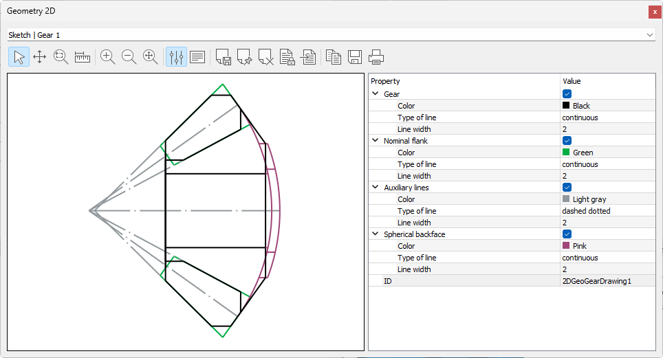
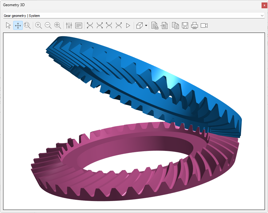
ZC1 Bevel gear geometry
Geometry according to DIN 3971 and ISO 23509
Blank dimensions of straight, helix- or spiral bevel gears
Conventional manufacturing process, Klingelnberg or Gleason
Conversion of Gleason Dimension Sheets for conical (Gleason) and uniform tooth depth (Klingelnberg, Oerlikon) to DIN 3971 and vice versa
Rough sizing macrogeometry
Calculation of the involute point
Separate verification of the inside and outside tooth form (toe/heel)
Rights: Z07, Z07m, Z07s1
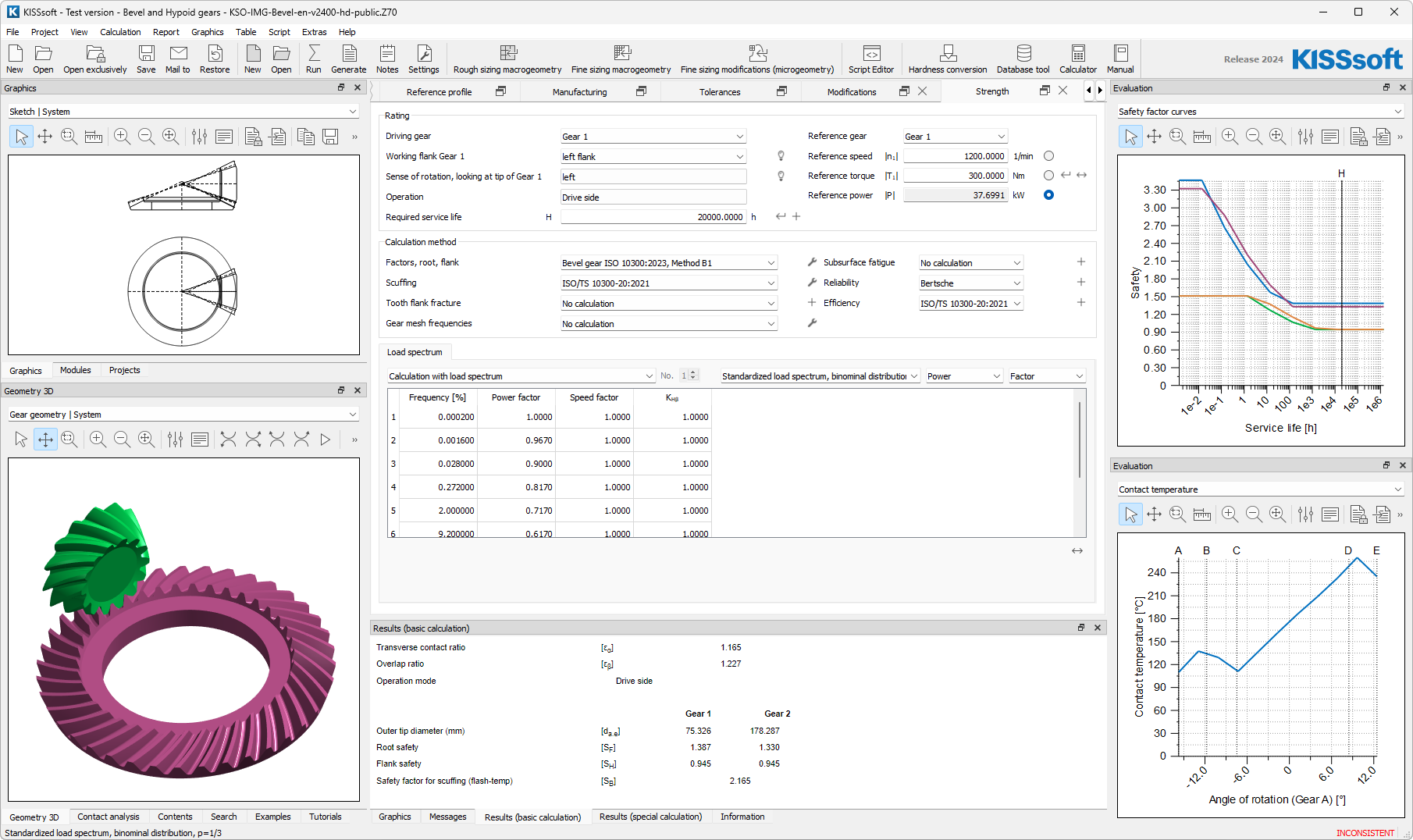
ZC2 Strength according to ISO 10300:2023 and ISO 10300:2001 for bevel gears
Method B and C
Calculation of scuffing for hypoid gears according to ISO/TS 10300-20:2021
Rights: Z07e
Module List B2 (Expert)
Module List B2 (Expert)
ZC1 Bevel gear geometry
Geometry according to DIN 3971 and ISO 23509
Blank dimensions of straight, helix- or spiral bevel gears
Conventional manufacturing process, Klingelnberg or Gleason
Conversion of Gleason Dimension Sheets for conical (Gleason) and uniform tooth depth (Klingelnberg, Oerlikon) to DIN 3971 and vice versa
Rough sizing macrogeometry
Calculation of the involute point
Separate verification of the inside and outside tooth form (toe/heel)
Rights: Z07, Z07m, Z07s1
ZC2 Strength according to ISO 10300:2023 and ISO 10300:2001 for bevel gears
Method B and C
Calculation of scuffing for hypoid gears according to ISO/TS 10300-20:2021
Rights: Z07e
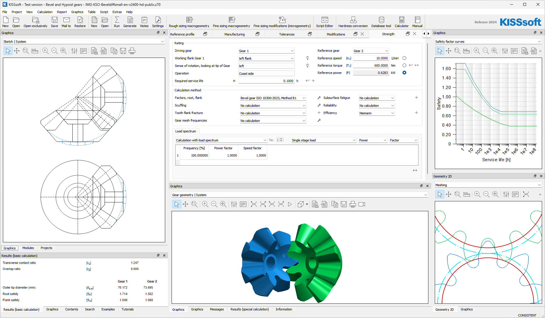
ZC12
Fine sizing of macrogeometry for bevel and hypoid gears
Production-specific criteria for forged differential bevel gears
Rights: Z07n
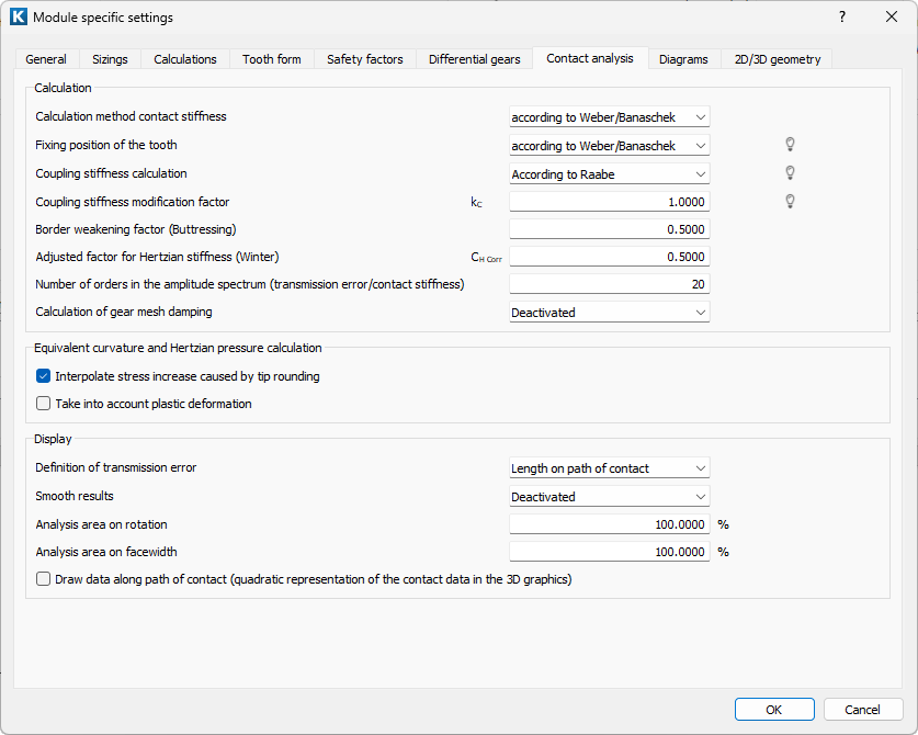
ZC30 Contact analysis under load
for bevel gears with straight, helical or spiral teeth
Taking into account the microgeometry
Graphical display of the results in the excitation force, efficiency, forces and stresses groups
Calculation of contact lines, transmission error and stress ratios
Display of the load-free contact pattern and the assembly contact pattern
Wear calculation
Tooth flank fracture according to ISO/DTS 10300-4:2019 (draft) (requires module ZZ4)
Calculation of VHJ misalignment values and axis angle error directly from the shaft deformation
Calculation of the excitation force according to FVA-No. 487 1.2.3
Rights: Z24, Z25, Z27, Z32c, Z35, Z36, Z39a, Z39b, Z39c, Z39d and K05w
General Description
General Description
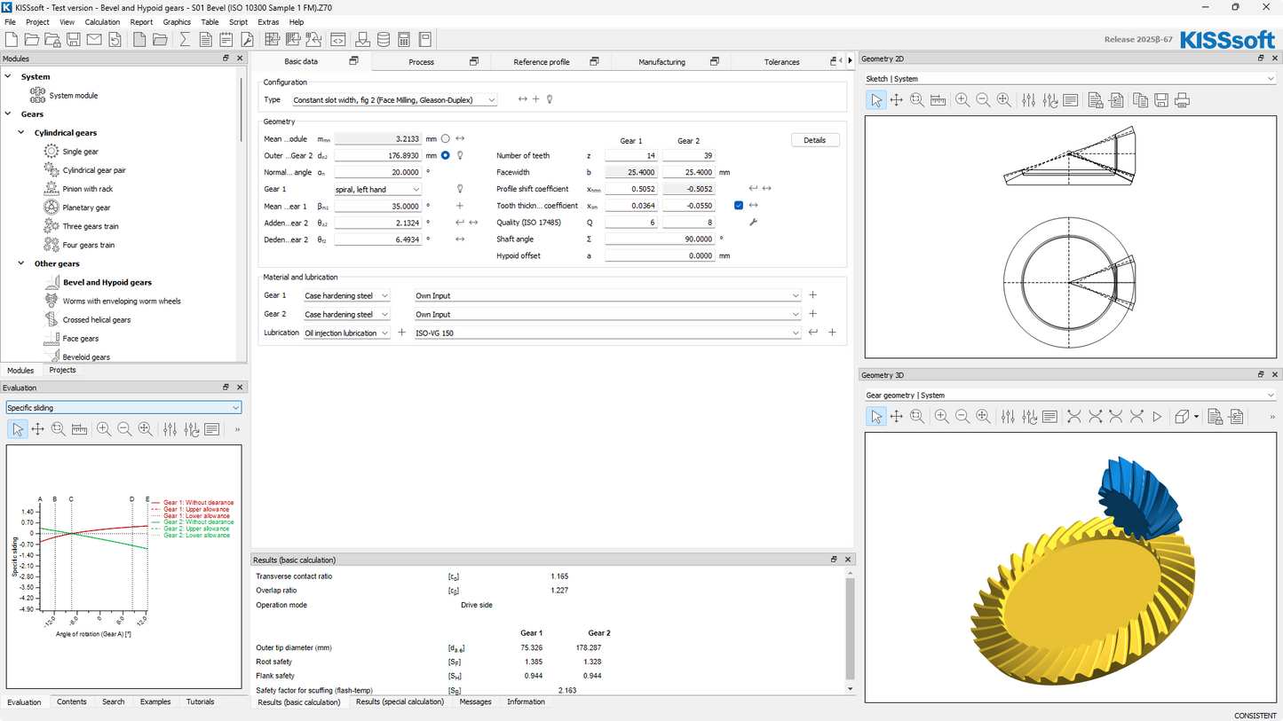
General
- Strength, life and reliability rating for nominal load and load spectrum
- Database for reference profile and tolerances
- Different geometry configurations with uniform tooth depth, constant slot width, modified slot width, different root and tip apex positions
- For spur, helical, zerol or spiral bevel gears
- Rough and fine sizing function, fine sizing function for modifications
- Calculation of measurement grid for Klingelnberg, Gleason or Zeiss gear tester
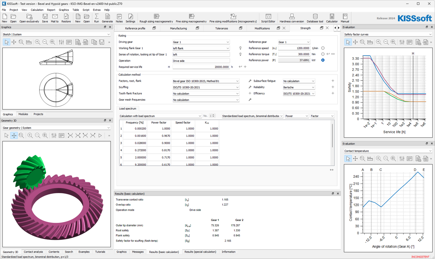
Strength rating
- Strength rating along ISO 10300, DIN 3991, AGMA 2003, KN3028 / KN3030 for Cyclo-Palloid gears and along KN3025 / KN3030 for Palloid gears
- Hypoid gear calculation along KN3029 / KN3030 for Cyclo-Palloid gears, KN3026 for Palloid gears, ISO 10300
- Plastic gear rating along VDI 2545 or Niemann, static strength rating and rating of differential planetary gears
- Efficiency along Wech, Niemann, ISO/TS 1300-20
- Flank breakage calculation along ISO/DTS 10300-4
- Scuffing rating along DIN 3990-4, ISO/TS 6336-20, ISO/TS 6336-21, ISO/TS 10300-21
Manufacturing
- For face hobbed or face milled gears
- Considering Klingelnberg machine list
- Accurate 3D gear geometry for CNC machining, based on planar involute geometry
- No load tooth contact analysis considering lead and profile modifications
No load tooth contact
- Calculated of loaded tooth contact with low load
- Considers all gear modifications
- Direct input of misalignment values
- For verification of contact patterns after manufacturing
Loaded tooth contact analysis
- LTCA of spur, helical and spiral bevel gears
- For nominal load or with consideration of KA and Kv and for load spectrum
- Using slice model
- Line load distribution over whole face width (contact pattern under load)
- Momentary line load distribution as contact lines for different mesh positions
Bevel gear transmission error
- Loaded or non-loaded (lightly loaded) TE
- PPTE values
- FFT of transmission error
Further load distribution-based results
- Flash and contact temperature
- Scuffing safety factor
- Flank fracture safety factor
- Micropitting (adapted from cylindrical gear calculation)
Contact for misaligned systems
- Input of HGV misalignment
- Input of shaft angle deviation
- For drive and coast side
- Considering housing, bearing and shaft deformation
Tooth flank fracture calculation
- Calculated hardness distribution
- Hardness distribution input from measurements
- Calculation along ISO/DTS 6336-4 and Annast
Differential gears
- Fine sizing of differential gears
- LTCA for spur gears with modifications
Share